| Rated thermal current (A) |
AC 380V | |||
| HR3 front side lever transmission mechanism type |
HR3 front center lever transmission mechanism type |
HR3 side operating handle type | HR3 panelless front side lever transmission mechanism type |
|
| 100 | HR3-100/31 | HR3-100/32 | HR3-100/33 | HR3-100/34 |
| 200 | HR3-200/31 | HR3-200/32 | HR3-200/33 | HR3-200/34 |
| 400 | HR3-400/31 | HR3-400/32 | HR3-400/33 | HR3-400/34 |
| 600 | HR3-600/31 | HR3-600/32 | HR3-600/33 | HR3-600/34 |
| 1000 | HR3-1000/31 | HR3-1000/32 | HR3-1000/33 | HR3-1000/34 |
| Model | Rated working voltage Ue (V) |
Rated insulation voltage Ui (V) |
Rated working current Ie (A) |
Conventional heating current Ith (A) |
Matched fuse |
| HR3-100 | 380 | 660 | 100 | 100 | RT0-100 |
| HR3-200 | 200 | 200 | RT0-200 | ||
| HR3-400 | 400 | 400 | RT0-400 | ||
| HR3-600 | 600 | 600 | RT0-600 | ||
| HR3-1000 | 1000 | 1000 | RT0-1000 |

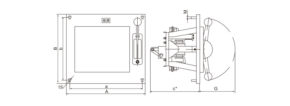
| Model | Dimensions | Installation dimensions | ||||||
| A | B | C* | G | a | b | φc | M | |
| HR3-100/31 | 400 | 400 | 275 | 266 | 360 | 360 | 12 | 10 |
| HR3-200/31 | 400 | 400 | 275 | 266 | 360 | 360 | 12 | 10 |
| HR3-400/31 | 400 | 400 | 275 | 266 | 360 | 360 | 12 | 10 |
| HR3-600/31 | 450 | 400 | 325 | 266 | 410 | 360 | 12 | 10 |
| HR3-1000/31 | 500 | 400 | 350 | 266 | 450 | 360 | 12 | 10 |
Note: C* dimension is the dimension when the connecting rod is in the maximum position after the switch is turned on.

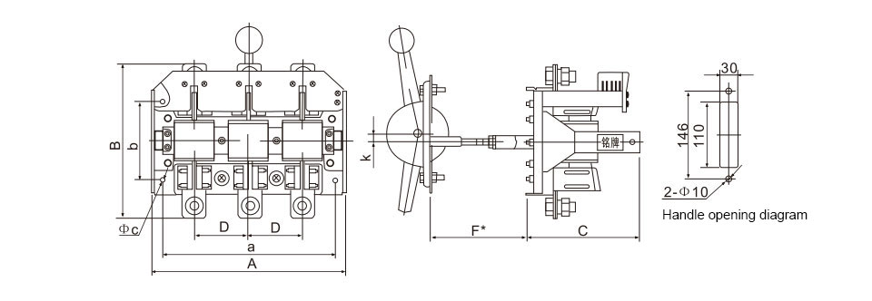
| Model | Dimensions | Installation dimensions | |||||||
| A | B | C | D | F* | a | b | φc | K | |
| HR3-100/32 | 250 | 192 | 185 | 60 | 250 | 215 | 130 | 7 | 12 |
| HR3-200/32 | 270 | 205 | 185 | 70 | 250 | 235 | 130 | 7 | 12 |
| HR3-400/32 | 290 | 222 | 185 | 80 | 250 | 255 | 130 | 7 | 12 |
| HR3-600/32 | 320 | 255 | 185 | 90 | 250 | 285 | 130 | 7 | 12 |
| HR3-1000/32 | 410 | 365 | 270 | 115 | 350 | 350 | 250 | 7 | 12 |
Note: Dimension F* is the dimension when the connecting rod is in the maximum position after the switch is turned on.

| Model | Dimensions | Installation dimensions | |||||||
| A | B | C | D | F* | a | b | φc | H | |
| HR3-100/33 | 250 | 200 | 185 | 60 | 75 | 215 | 160 | 7 | 78 |
| HR3-200/33 | 270 | 205 | 185 | 70 | 75 | 235 | 160 | 7 | 78 |
| HR3-400/33 | 290 | 222 | 185 | 80 | 75 | 255 | 160 | 7 | 78 |
| HR3-600/33 | 320 | 255 | 185 | 90 | 75 | 285 | 160 | 7 | 78 |
| HR3-1000/33 | 410 | 365 | 270 | 115 | 75 | 350 | 250 | 9 | 102 |
Note: Dimension F* is the dimension when the connecting rod is in the maximum position after the switch is turned on.

| Model | Dimensions | Installation dimensions | ||||||||
| A | B | C | D | F* | a | b | φc | H | K | |
| HR3-100/34 | 250 | 200 | 250 | 60 | 75 | 215 | 160 | 7 | 78 | 12 |
| HR3-200/34 | 270 | 205 | 250 | 70 | 75 | 235 | 160 | 7 | 78 | 12 |
| HR3-400/34 | 290 | 222 | 250 | 80 | 75 | 255 | 160 | 7 | 78 | 12 |
| HR3-600/34 | 320 | 255 | 250 | 90 | 75 | 285 | 160 | 7 | 78 | 12 |
| HR3-1000/34 | 410 | 365 | 350 | 115 | 75 | 350 | 250 | 9 | 102 | 12 |
Note: Dimension F* is the dimension when the connecting rod is in the maximum position after the switch is turned on.
GET A QUOTE