3.1 Rated insulation voltage: 690V
3.2 Rated working voltage: 380V, 660V
3.3 Rated working current!
380V: 100A, 200A, 400A, 630A
660V: 100A, 200A, 315A, 425A
3.4 Switch connection and disconnection capacity and rated fuse short-circuit current (see Table 1)
3.5 The mechanical life of the switch is 3000 times (100A, 200A) and 1000 times (400A, 630A)
3.6 The electrical life of the switch is 600 times (100A, 200A) and 200 times (400A, 630A) respectively. The connection and disconnection conditions are as shown in (Table 2).
3.7 The rated working voltage of the auxiliary switch (LX19K) is AC 380V, the rated heating current is 6A, and the rated control capacity is 300VA.
Table1
| Rated working voltage Ue (V) |
Conventional heating current Ie (A) |
Use category | Rated making and breaking capacity | Rated short-circuit current | ||||||||
| Connect | Connect | Connect | Disconnect | Disconnect | Disconnect | Number of operating cycles |
RMS current (kA) |
COSφ | Number of making and breaking times |
|||
| I/Ie | U/Ue | COSφ | lc/le | Ur/Ue | COSφ | |||||||
| 380 | 100 | AC-23B | 10 | 1.05 | 0.45 | 8 | 1.05 | 0.45 | 5 | 50 | 0.25 | 1 time each |
| 200 | AC-23B | 10 | 1.05 | 0.35 | 8 | 1.05 | 0.35 | 3 | 50 | 0.25 | 1 time each | |
| 400 | AC-23B | 10 | 1.05 | 0.35 | 8 | 1.05 | 0.35 | 3 | 50 | 0.25 | 1 time each | |
| 630 | AC-23B | 10 | 1.05 | 0.35 | 8 | 1.05 | 0.35 | 3 | 50 | 0.25 | 1 time each | |
| 660 | 100 | AC-22B | 3 | 1.05 | 0.65 | 3 | 1.05 | 0.65 | 5 | 50 | 0.25 | 1 time each |
| 200 | AC-22B | 3 | 1.05 | 0.65 | 3 | 1.05 | 0.65 | 5 | 50 | 0.25 | 1 time each | |
| 315 | AC-22B | 3 | 1.05 | 0.65 | 3 | 1.05 | 0.65 | 5 | 50 | 0.25 | 1 time each | |
| 400 | AC-22B | 3 | 1.05 | 0.65 | 3 | 1.05 | 0.65 | 5 | 50 | 0.25 | 1 time each | |
Table2
| Rated working voltage (V) | Use category | Connect | Connect | Connect | Disconnect | Disconnect | Disconnect |
| I/Ie | U/Ue | COSφ | lc/le | Ur/Ue | COSφ | ||
| 380 | AC-23B | 1 | 1 | 0.65 | 1 | 1 | 0.65 |
| 660 | AC-22B | 1 | 1 | 0.8 | 1 | 1 | 0.8 |
3.8. The matching relationship between switches and fuses (see Table 3)
Table3
| Switch rated thermal current (A) | Matching fuse number | Melt current value (A) |
| 100 | NT00 | 4、6、10、16、20、25、32、35、40、50、63、80、100、125、160 |
| 200 | NT1 | 80、100、125、160、200、224、250 |
| 400 | NT2 | 125、160、200、224、250、300、315、355、400 |
| 630 | NT3 | 315、355、400、425、500、630 |
Note: When the switch is used in the motor circuit, the fuse rated current is allowed to be greater than the switch's agreed heating current
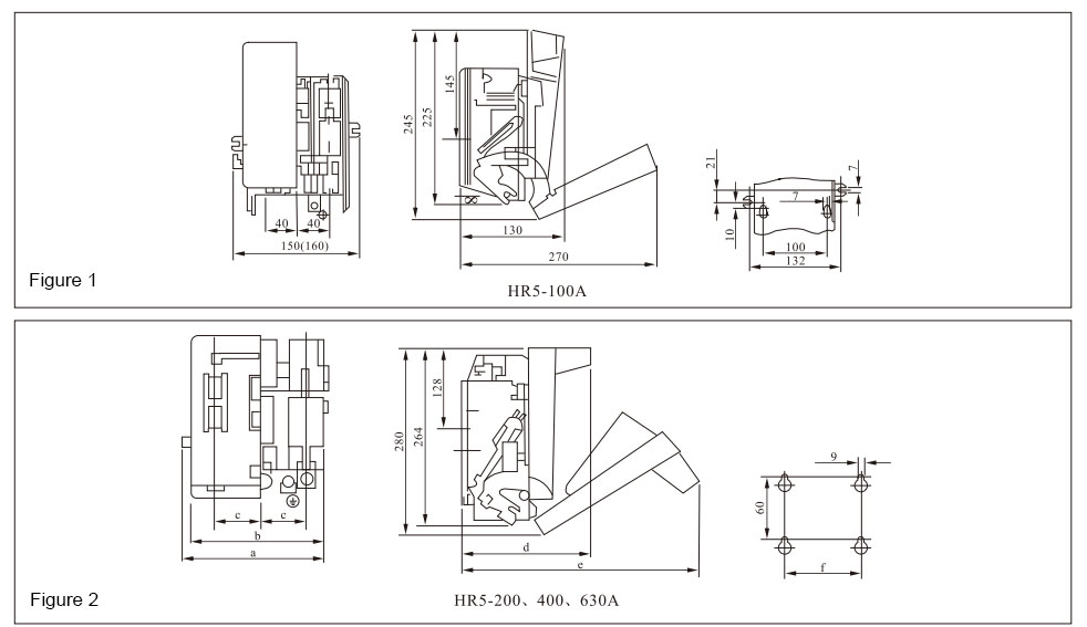
4. Switch appearance and installation dimensions (see Table 4, Figure 1, Figure 2)
Table4
| Model | Dimensions (mm) | |||||
| a | b | c | d | e | f(Mounting hole distance) | |
| HR5-200/20 | 203 | 203 | 62 | 193 | 342 | 130 |
| HR5-200/30 | 203 | 203 | 62 | 193 | 342 | 130 |
| HR5-200/31 | 220 | 203 | 62 | 193 | 342 | 130 |
| HR5-400/20 | 226 | 226 | 70 | 210 | 358 | 130 |
| HR5-400/30 | 226 | 226 | 70 | 210 | 358 | 130 |
| HRS-400/31 | 242 | 226 | 70 | 210 | 358 | 130 |
| HR5-630/20 | 272 | 272 | 85 | 224 | 372 | 200 |
| HR5-630/30 | 272 | 272 | 85 | 224 | 372 | 200 |
| HR5-630/31 | 290 | 272 | 85 | 224 | 372 | 200 |

GET A QUOTE