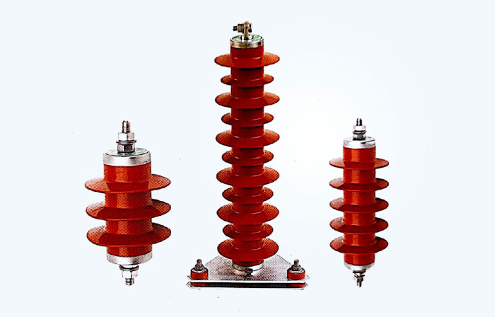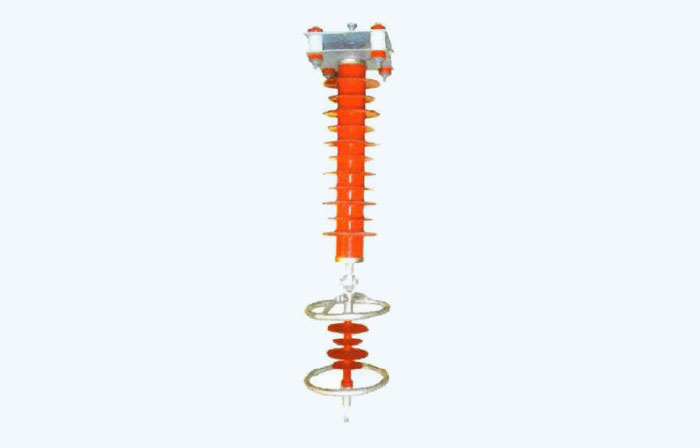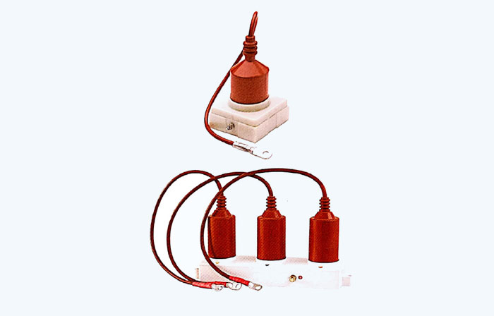
Due to some particularities of my country's medium-voltage resistors (3~66kV), conventional medium-voltage arresters are not sensitive to overvoltage in this type of operation and cannot provide protection. TBP three-phase combined overvoltage protector (also known as YH three-phase combined arrester) is a new product developed to solve this problem.
This type of product adopts a four-star connection (commonly known as a three-way connection) and sets a common neutral point, which can not only greatly reduce phase-to-phase overvoltage, but also qualitatively improve the relative-to-ground protection level, which truly plays a role in the vacuum switch operation. Effective limitation of overvoltage.
Our company's products are composite insulation, with small and compact structure, and are integrally vulcanized and fully enclosed. It adopts high-quality metal oxide valve plate and self-blowing special gap, which has high working performance, safety and convenience. It is especially suitable for use with different types of medium-voltage complete switch cabinets such as KYN, XGN, GBC, JYN, GZS, etc., or directly installed in small box-type substations.
This product is used in AC medium voltage 3~66KV power systems to prevent operating overvoltage mainly generated by vacuum switches from damaging electrical equipment. It also has the function of lightning protection.
Our company's product technical standards mainly refer to GB 11032-2000 "AC Integrated Metal Oxide Surge Arrester", JB/T 9672-2005 "Surge Arrester for Metal Objects with Series Gap" and DL 620-1997 "Overvoltage Protection and Protection of AC Electrical Devices" "Insulation Cooperation" standard is formulated and implemented in accordance with JB/Factory 10496-2005 "AC three-phase combined gap metal oxide arrester" and JBT 10609-2006 "AC three-phase combined gap metal oxide arrester".
3.1 The normal usage conditions of conventional products are as follows:
1) Ambient temperature: not higher than +40C, not lower than -40C;
2) Altitude: no more than 3000m;
3) Power frequency: 502Hz; 602HZ;
4) Maximum wind speed: 35m/s;
5) Cleaning-free conditions: moderately dirty areas and below;
6) For products without gaps, the long-term applied power frequency voltage shall not exceed the continuous operating voltage of the protector;
7) For products with gaps, the short-term power frequency voltage increase at the installation point shall not exceed the rated voltage of the protector.
3.2 For long-term use under the following abnormal conditions, the protector needs to be specially made and should be stated when ordering:
1) The temperature or altitude exceeds the standard (such as plateau, tropical, cold zone, fully enclosed cabinet, close to electric furnace, etc.);
2) The use environment contains severe moisture or corrosive gas impurities (such as water, salt fields, chemical plants, etc.)
3) Strong ultraviolet radiation (such as plateaus, dry areas with strong sunshine, etc.);
4) Extremely polluted areas (such as mining working faces, construction site working faces, etc.).
There are no strict national standard definition rules for this product. Currently, each manufacturing company defines its own product according to the model applied for by the National Testing Center. The product models of each company vary greatly for the same purpose. Manufacturers that have not yet obtained the type certification certificate usually refer to the general provisions of JB/T 8459-2006 "Method for Preparing Surge Arrester Product Models" for extended definitions.
The national certification model of our company's products is TBP, and its model is defined as follows:
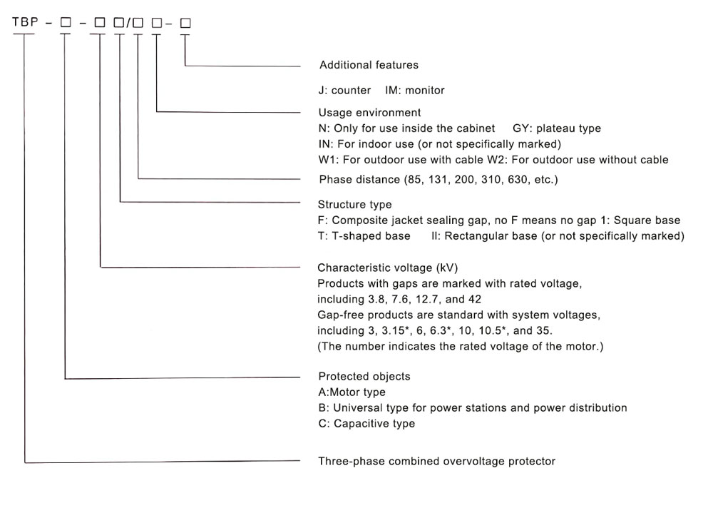
At the same time, this product can also be expanded and defined according to the compilation principles of JB/T 8459-2006 "Product Model Compilation Method of Lightning Arrester". The specific model definition is as follows:
| Voltage level | use | Usage environment | Regular TBP model | Gap type | Nominal residual voltage (kV) | 2000μS square wave flow capacity (A) | 4/10 Large current withstand capability (kA) | ||||
| Protector rated voltage (kV) effective value | The effective value of power frequency discharge voltage (kV) is not less than | 1.2/50 The peak value of impulse discharge voltage (kV) is not greater than | Maximum conductivity current (μA) | 8/20 The peak value under lightning impulse current is not greater than | The peak value under 30/60 operating impulse current is not greater than | ||||||
| Relative to phase/relative to ground (only one number indicates that the phase and ground parameters are the same) | |||||||||||
| 3kV | For A type motor | indoor | TBP-A-3.8F/85 | 3.8 | 7.5 | 9.5 | 20 | 9.5 | 7.6 | 400 | 65 |
| TBP-A-3.8F/131 | 3.8 | 7.5 | 9.5 | 20 | 9.5 | 7.6 | 400/200 | 65/40 | |||
| outdoor | TBP-A-3.8F/100W1 | 3.8 | 7.5 | 9.5 | 20 | 9.5 | 7.6 | 400 | 65 | ||
| TBP-A-3.8F/280W2 | 3.8 | 7.5 | 9.5 | 20 | 9.5 | 7.6 | 400 | 65 | |||
| Type B substation is universal |
indoor | TBP-B-3.8F/85 | 3.8 | 8.0 | 12.0 | 20 | 12.0 | 10.2 | 400 | 65 | |
| TBP-B-3.8F/131 | 3.8 | 8.0 | 12.0 | 20 | 12.0 | 10.2 | 400/200 | 65/40 | |||
| outdoor | TBP-B-3.8F/100W1 | 3.8 | 8.0 | 12.0 | 20 | 12.0 | 10.2 | 400 | 65 | ||
| TBP-B-3.8F/280W2 | 3.8 | 8.0 | 12.0 | 20 | 12.0 | 10.2 | 400 | 65 | |||
| For C type capacitors |
indoor | TBP-B-3.8F/85 | 3.8 | 8.0 | 12.0 | 20 | 12.0 | 9.6 | 400 | 65 | |
| TBP-B-3.8F/131 | 3.8 | 8.0 | 12.0 | 20 | 12.0 | 9.6 | 400/200 | 65/40 | |||
| outdoor | TBP-C-3.8F/100W1 | 3.8 | 8.0 | 12.0 | 20 | 12.0 | 9.6 | 400 | 65 | ||
| TBP-C-3.8F/280W2 | 3.8 | 8.0 | 12.0 | 20 | 12.0 | 9.6 | 400 | 65 | |||
| 6kV | For A type motor | indoor | TBP-A-7.6F/85 | 7.6 | 15.0 | 18.7 | 20 | 18.7 | 15.0 | 400 | 65 |
| TBP-A-7.6F/131 | 7.6 | 15.0 | 18.7 | 20 | 18.7 | 15.0 | 400/200 | 65/40 | |||
| outdoor | TBP-A-7.6F/100W1 | 7.6 | 15.0 | 18.7 | 20 | 18.7 | 15.0 | 400 | 65 | ||
| TBP-A-7.6F/280W2 | 7.6 | 15.0 | 18.7 | 20 | 18.7 | 15.0 | 400 | 65 | |||
| Type B substation is universal |
indoor | TBP-B-7.6F/85 | 7.6 | 16.0 | 24.0 | 20 | 18.7 | 20.4 | 400 | 65 | |
| TBP-B-7.6F/131 | 7.6 | 16.0 | 24.0 | 20 | 24.0 | 20.4 | 400/200 | 65/40 | |||
| outdoor | TBP-B-7.6F/100W1 | 7.6 | 16.0 | 24.0 | 20 | 24.0 | 20.4 | 400 | 65 | ||
| TBP-B-7.6F/280W2 | 7.6 | 16.0 | 24.0 | 20 | 24.0 | 20.4 | 400 | 65 | |||
| For C type capacitors |
indoor | TBP-C-7.6F/85 | 7.6 | 16.0 | 24.0 | 20 | 24.0 | 19.5 | 400 | 65 | |
| TBP-C-7.6F/131 | 7.6 | 16.0 | 24.0 | 20 | 24.0 | 19.5 | 400/200 | 65/40 | |||
| outdoor | TBP-C-7.6F/100W1 | 7.6 | 16.0 | 24.0 | 20 | 24.0 | 19.5 | 400 | 65 | ||
| TBP-C-7.6F/280W2 | 7.6 | 16.0 | 24.0 | 20 | 24.0 | 19.5 | 400 | 65 | |||
| 10kV | For A type motor | indoor | TBP-A-12.7F/85 | 12.7 | 25.0 | 31.0 | 20 | 31.0 | 25.0 | 400 | 65 |
| TBP-A-12.7F/131 | 12.7 | 25.0 | 31.0 | 20 | 31.0 | 25.0 | 400/200 | 65/40 | |||
| outdoor | TBP-A-12.7F/100W1 | 12.7 | 25.0 | 31.0 | 20 | 31.0 | 25.0 | 400 | 65 | ||
| TBP-A-12.7F/280W2 | 12.7 | 25.0 | 31.0 | 20 | 31.0 | 25.0 | 400 | 65 | |||
| Type B substation is universal |
indoor | TBP-B-12.7F/85 | 12.7 | 26.0 | 41.0 | 20 | 41.0 | 35.0 | 400 | 65 | |
| TBP-B-12.7F/131 | 12.7 | 26.0 | 41.0 | 20 | 41.0 | 35.0 | 400/200 | 65/40 | |||
| outdoor | TBP-B-12.7F/100W1 | 12.7 | 26.0 | 41.0 | 20 | 41.0 | 35.0 | 400 | 65 | ||
| TBP-B-12.7F/280W2 | 12.7 | 26.0 | 41.0 | 20 | 41.0 | 35.0 | 400 | 65 | |||
| For C type capacitors |
indoor | TBP-C-12.7F/85 | 12.7 | 26.0 | 41.0 | 20 | 41.0 | 33.0 | 400 | 65 | |
| TBP-C-12.7F/131 | 12.7 | 26.0 | 41.0 | 20 | 41.0 | 33.0 | 400/200 | 65/40 | |||
| outdoor | TBP-C-12.7F/100W1 | 12.7 | 26.0 | 41.0 | 20 | 41.0 | 33.0 | 400 | 65 | ||
| TBP-C-12.7F/280W2 | 12.7 | 26.0 | 41.0 | 20 | 41.0 | 33.0 | 400 | 65 | |||
| 35kV | Type B substation is universal |
indoor | TBP-B-42F/200 | 42 | 80 | 124 | 20 | 124 | 105.4 | 400 | 65 |
| TBP-B-42F/310 | 42 | 80 | 124 | 20 | 124 | 105.4 | 400 | 65 | |||
| outdoor | TBP-B-42F/400W1 | 42 | 80 | 124 | 20 | 124 | 105.4 | 400 | 65 | ||
| TBP-B-42F/630W2 | 42 | 80 | 124 | 20 | 124 | 105.4 | 400 | 65 | |||
| For C type capacitors |
indoor | TBP-C-42F/200 | 42 | 80 | 124 | 20 | 124 | 100 | 400 | 65 | |
| TBP-C-42F/310 | 42 | 80 | 124 | 20 | 124 | 100 | 400 | 65 | |||
| outdoor | TBP-C-42F/400W1 | 42 | 80 | 124 | 20 | 124 | 100 | 400 | 65 | ||
| TBP-C-42F/630W2 | 42 | 80 | 124 | 20 | 124 | 100 | 400 | 65 | |||
| Voltage level | use | Usage environment | Simplified TBP model | No gap type | Nominal residual voltage (kV) | 2000μS square wave flow capacity (A) 400 | 4/10 Large current withstand capability (kA) | ||||
| Protector rated voltage (kV) effective value | Protector continuous operating voltage (kV) 3.15 | DC 1mA reference voltage (kV) is not less than | Maximum leakage at 0.75 times DC reference voltage (μA) | 8/20 The peak value under lightning impulse current is not greater than | The peak value under 30/60 operating impulse current is not greater than | ||||||
| Relative to phase/relative to ground (only one number indicates that the phase and ground parameters are the same) | |||||||||||
| 3kV | For A type motor | indoor | TBP-A-3.15/85 | 4 | 3.15 | 7.0/5.7 | 50 | 11.5/9.5 | 9.4/7.6 | 400/200 | 65 |
| TBP-A-3.15/131 | 4 | 3.15 | 7.0/5.7 | 50 | 11.5/9.5 | 9.4/7.6 | 400 | 65/40 | |||
| outdoor | TBP-A-3.15/100W1 | 4 | 3.15 | 7.0/5.7 | 50 | 11.5/9.5 | 9.4/7.6 | 400 | 65 | ||
| TBP-A-3.15/280W2 | 4 | 4.0 | 7.0/5.7 | 50 | 11.5/9.5 | 9.4/7.6 | 400 | 65 | |||
| Type B substation is universal |
indoor | TBP-B-3/85 | 5 | 4.0 | 7.5/7.2 | 50 | 13.5 | 11.5 | 400/200 | 65 | |
| TBP-B-3/131 | 5 | 4.0 | 7.5/7.2 | 50 | 13.5 | 11.5 | 400 | 65/40 | |||
| outdoor | TBP-B-3/100W1 | 5 | 4.0 | 7.5/7.2 | 50 | 13.5 | 11.5 | 400 | 65 | ||
| TBP-B-3/280W2 | 5 | 4.0 | 7.5/7.2 | 50 | 13.5 | 11.5 | 400 | 65 | |||
| For C type capacitors |
indoor | TBP-B-3/85 | 5 | 4.0 | 7.5/7.2 | 50 | 13.5 | 10.5 | 400/200 | 65 | |
| TBP-B-3/131 | 5 | 4.0 | 7.5/7.2 | 50 | 13.5 | 10.5 | 400 | 65/40 | |||
| outdoor | TBP-C-3/100W1 | 5 | 4.0 | 7.5/7.2 | 50 | 13.5 | 10.5 | 400 | 65 | ||
| TBP-C-3/280W2 | 5 | 2.3 | 7.5/7.2 | 50 | 13.5 | 10.5 | 400 | 65 | |||
| O type | neutral point | TBP-O-2.13F | 3.15 | 6.3 | 3.4 | 50 | 6.0 | 5.0 | 400 | 65 | |
| 6kV | For A type motor | indoor | TBP-A-6.3/85 | 8 | 6.3 | 14.0/11.2 | 50 | 23.0/18.7 | 18.7/15.0 | 400/200 | 65 |
| TBP-A-6.3/131 | 8 | 6.3 | 14.0/11.2 | 50 | 23.0/18.7 | 18.7/15.0 | 400 | 65/40 | |||
| outdoor | TBP-A-6.3/100W1 | 8 | 6.3 | 14.0/11.2 | 50 | 23.0/18.7 | 18.7/15.0 | 400 | 65 | ||
| TBP-A-6.3/280W2 | 8 | 8.0 | 14.0/11.2 | 50 | 23.0/18.7 | 18.7/15.0 | 400 | 65 | |||
| Type B substation is universal |
indoor | TBP-B-6/85 | 10 | 8.0 | 15.0/14.4 | 50 | 27.0 | 23.0 | 400/200 | 65 | |
| TBP-B-6/131 | 10 | 8.0 | 15.0/14.4 | 50 | 27.0 | 23.0 | 400 | 65/40 | |||
| outdoor | TBP-B-6/100W1 | 10 | 8.0 | 15.0/14.4 | 50 | 27.0 | 23.0 | 400 | 65 | ||
| TBP-B-6/280W2 | 10 | 8.0 | 15.0/14.4 | 50 | 27.0 | 23.0 | 400 | 65 | |||
| For C type capacitors |
indoor | TBP-C-6/85 | 10 | 8.0 | 15.0/14.4 | 50 | 27.0 | 21.0 | 400/200 | 65 | |
| TBP-C-6/131 | 10 | 8.0 | 15.0/14.4 | 50 | 27.0 | 21.0 | 400 | 65/40 | |||
| outdoor | TBP-C-6/100W1 | 10 | 8.0 | 15.0/14.4 | 50 | 27.0 | 21.0 | 400 | 65 | ||
| TBP-C-6/280W2 | 10 | 4.6 | 15.0/14.4 | 50 | 27.0 | 21.0 | 400 | 65 | |||
| O type | neutral point | TBP-0-4.6F | 6.3 | 10.5 | 6.8 | 50 | 12.0 | 10.0 | 400 | 65 | |
| 10kV 35kV |
For A type motor | indoor | TBP-A-10.5/85 | 13.5 | 10.5 | 23.2/18.6 | 50 | 38.0/31.0 | 31.0/25.0 | 400/200 | 65 |
| TBP-A-10.5/131 | 13.5 | 10.5 | 23.2/18.6 | 50 | 38.0/31.0 | 31.0/25.0 | 400 | 65/40 | |||
| outdoor | TBP-A-10.5/100W1 | 13.5 | 10.5 | 23.2/18.6 | 50 | 38.0/31.0 | 31.0/25.0 | 400 | 65 | ||
| TBP-A-10.5/280W2 | 13.5 | 13.6 | 23.2/18.6 | 50 | 38.0/31.0 | 31.0/25.0 | 400 | 65 | |||
| Type B substation is universal |
indoor | TBP-B-10/85 | 17 | 13.6 | 25.0/24.0 | 50 | 45.0 | 38.3 | 400/200 | 65 | |
| TBP-B-10/131 | 17 | 13.6 | 25.0/24.0 | 50 | 45.0 | 38.3 | 400 | 65/40 | |||
| outdoor | TBP-B-10/100W1 | 17 | 13.6 | 25.0/24.0 | 50 | 45.0 | 38.3 | 400 | 65 | ||
| TBP-B-10/280W2 | 17 | 13.6 | 25.0/24.0 | 50 | 46.0 | 38.3 | 400 | 65 | |||
| For C type capacitors |
indoor | TBP-C10/85 | 17 | 13.6 | 25.0/24.0 | 50 | 46.0 | 35.0 | 400/200 | 65 | |
| TBP-C-10/131 | 17 | 13.6 | 25.0/24.0 | 50 | 46.0 | 35.0 | 400 | 65/40 | |||
| outdoor | TBP-C-10/100W1 | 17 | 13.6 | 25.0/24.0 | 50 | 46.0 | 35.0 | 400 | 65 | ||
| TBP-C-10/280W2 | 17 | 7.6 | 25.0/24.0 | 50 | 46.0 | 35.0 | 400 | 65 | |||
| O type | neutral point | TBP-0-7.6F | 10.5 | 40.8 | 11.4 | 50 | 19.0 | 15.9 | 400 | 65 | |
| Type B substation is universal |
indoor | TBP-B-35/200 | 51 | 40.8 | 84/73 | 50 | 150/134 | 134/114 | 400 | 65 | |
| TBP-B-35/310 | 51 | 40.8 | 84/73 | 50 | 150/134 | 134/114 | 400 | 65 | |||
| outdoor | TBP-B-35/400W1 | 51 | 40.8 | 84/73 | 50 | 150/134 | 134/114 | 400 | 65 | ||
| TBP-B-35/630W2 | 51 | 40.8 | 84/73 | 50 | 150/134 | 134/114 | 400 | 65 | |||
| For C type capacitors |
indoor | TBP-C-35/200 | 51 | 40.8 | 84/73 | 50 | 150/134 | 122/105 | 400 | 65 | |
| TBP-C-35/310 | 51 | 40.8 | 84/73 | 50 | 150/134 | 122/105 | 400 | 65 | |||
| outdoor | TBP-C-35/400W1 | 51 | 40.8 | 84/73 | 50 | 150/134 | 122/105 | 400 | 65 | ||
| TBP-C-35/630W2 | 51 | 84/73 | 50 | 150/134 | 122/105 | 65 | |||||
| use | System nominal voltage (kV) | Standard model | Protector rated voltage (kV) effective value | No gap type | Gap type | Nominal residual voltage (kV) | 2000μS square wave flow capacity (A) 400 | |||||
| Protector continuous operating voltage (kV) 3.15 | DC 1mA reference voltage (kV) is not less than | Maximum leakage at 0.75 times DC reference voltage (μA) | The effective value of power frequency discharge voltage (kV) is not less than | 1.2/50 The peak value of impulse discharge voltage (kV) is not greater than | Maximum conductivity current (μA) | 8/20 The peak value under lightning impulse current is not greater than | The peak value under 30/60 operating impulse current is not greater than | |||||
| Relative to phase/relative to ground (only one number indicates that the phase and ground parameters are the same) | ||||||||||||
| For S type power distribution | 3 | YH5WS-5/15×5/15 | 5 | 4.0 | 8.0/7.5 | 50 | - | - | - | 15.0 | 12.8 | 100 |
| 3 | YH5CS-3.8/15×3.8/13.5 | 3.8 | - | - | - | 9.0 | 15.0/13.5 | 20 | 15.0/13.5 | 11.4/10.2 | 100 | |
| 6 | YH5WS-10/30×10/30 | 10 | 8.0 | 16.0/15.0 | 50 | - | - | - | 30.0 | 23.0 | 100 | |
| 6 | YH5CS-7.6/27×7.6/24.5 | 7.6 | - | - | - | 16.0 | 27.0/24.5 | 20 | 27.0/24.5 | 22.5/20.4 | 100 | |
| 10 | YH5WS-17/50×17/50 | 17 | 13.6 | 26.5/25.0 | 50 | - | - | - | 50.0 | 38.3 | 100 | |
| 10 | YH5CS-12.7/45×12.7/41 | 12.7 | - | - | - | 26.0 | 45.0/41.0 | 20 | 45.0/41.0 | 38.4/35.0 | 100 | |
| For Z type power station | 3 | YH5WZ-5/13.5×5/13.5 | 5 | 4.0 | 7.5/7.2 | 50 | - | - | - | 13.5 | 11.5 | 150 |
| 3 | YH5CZ-3.8/12×3.8/12 | 3.8 | - | - | - | 8.0 | 12.0 | 20 | 12.0 | 10.2 | 150 | |
| 6 | YH5WZ-10/27×10/27 | 10 | 8.0 | 15.0/14.4 | 50 | - | - | - | 27.0 | 23.0 | 150 | |
| 6 | YH5CZ-7.6/24×7.6/24 | 7.6 | - | - | - | 16.0 | 24.0 | 20 | 24.0 | 20.4 | 150 | |
| 10 | YH5WZ-17/45×17/45 | 17 | 13.6 | 25.0/24.0 | 50 | - | - | - | 45.0 | 38.3 | 150 | |
| 10 | YH5CZ-12.7/41×12.7/41 | 12.7 | - | - | - | 26.0 | 41.0 | 20 | 41.0 | 35.0 | 150 | |
| 35 | YH5WZ-51/150×51/134 | 51 | 40.8 | 84/73 | 50 | - | - | - | 150/134 | 134/114 | 400 | |
| 35 | YH5CZ-42/124×42/124 | 42 | - | - | - | 80 | 124 | 20 | 124 | 105.4 | 400 | |
| R type capacitors use D type | 3 | YH5WR-5/13.5×5/13.5 | 5 | 4.0 | 7.5/7.2 | 50 | - | - | - | 13.5 | 10.5 | 400 |
| 3 | YH5CR-3.8/12×3.8/12 | 3.8 | - | - | - | 80 | 12.0 | 20 | 12.0 | 9.6 | 400 | |
| 6 | YH5WR-10/27×10/27 | 10 | 8.0 | 15.0/14.4 | 50 | - | - | - | 27.0 | 21.0 | 400 | |
| 6 | YH5CR-7.6/24×7.6/24 | 7.6 | - | - | - | 16.0 | 24.0 | 20 | 24.0 | 19.5 | 400 | |
| 10 | YH5WR-17/46×17/46 | 17 | 13.6 | 25.0/24.0 | 50 | - | - | - | 46.0 | 35.0 | 400 | |
| 10 | YH5CR-12.7/41×12.7/41 | 12.7 | - | - | - | 26.0 | 41.0 | 20 | 41.0 | 33.0 | 400 | |
| 35 | YH5WR-51/150×51/134 | 51 | 40.8 | 84/73 | 50 | - | - | - | 150/134 | 122/105 | 400 | |
| 35 | YH5CR-42/124×42/124 | 42 | - | - | - | 80 | 124 | 20 | 124 | 100 | 400 | |
| D type for generator | 3.15* | YH5WD-4/11.5×4/9.5 | 4 | 3.15 | 7.0/5.7 | 50 | - | - | - | 11.5/9.5 | 9.4/7.6 | 400 |
| 3.15* | YH5CD-3.8/9.5×3.8/9.5 | 3.8 | - | - | - | 7.5 | 9.5 | 20 | 9.5 | 7.6 | 400 | |
| 6.3* | YH5WD-8/23×8/18.7 | 8 | 6.3 | 14.0/11.2 | 50 | - | - | - | 23.0/18.7 | 18.7/15.0 | 400 | |
| 6.3* | YH5CD-7.6/18.7×7.6/18.7 | 7.6 | - | - | - | 15.0 | 18.7 | 20 | 18.7 | 15.0 | 400 | |
| 10.5* | YH5WD-13.5/38×13.5/31 | 13.5 | 10.5 | 23.2/18.6 | 50 | - | - | - | 38.0/31.0 | 31.0/25.0 | 400 | |
| 10.5* | YH5CD-12.7/31×12.7/31 | 12.7 | - | - | - | 25.0 | 31.0 | 20 | 31.0 | 25.0 | 400 | |
| For electric motor | 3.15* | YH2.5WD-4/11.5×4/9.5 | 4 | 3.15 | 7.0/5.7 | 50 | - | - | - | 11.5/9.5 | 9.4/7.6 | 200 |
| 3.15* | YH2.5CD-3.8/9.5×3.8/9.5 | 3.8 | - | - | - | 7.5 | 9.5 | 20 | 9.5 | 7.6 | 200 | |
| 6.3* | YH2.5WD-8/23×8/18.7 | 8 | 6.3 | 14.0/11.2 | 50 | - | - | - | 23.0/18.7 | 18.7/15.0 | 200 | |
| 6.3* | YH2.5CD-7.6/18.7×7.6/18.7 | 7.6 | - | - | - | 15.0 | 18.7 | 20 | 18.7 | 15.0 | 200 | |
| 10.5* | YH2.5WD-13.5/38×13.5/31 | 13.5 | 10.5 | 23.2/18.6 | 50 | - | - | - | 38.0/31.0 | 31.0/25.0 | 200 | |
| 10.5* | YH2.5CD-12.7/31×12.7/31 | 12.7 | - | - | - | 25.0 | 31.0 | 20 | 31.0 | 25.0 | 200 | |
Remark:
1. In the "System Nominal Voltage" column, the data with "" is the rated motor voltage corresponding to motor protection products.
2. Due to the many uses and voltage levels, the impulse current value corresponding to the 30/60 operating impulse residual voltage is not specifically specified. The current value is selected according to relevant standards.
3. Plateau prototype products must be specially produced and indicated by adding “GY” after the model number.
4. Most products can be equipped with counters, monitors and other accessories. If equipped with a counter, add "J" after the model number, and if equipped with a monitor, add "IM".
5. Since the phase partial pressure of combined products is extremely heavy and the charge rate is too high, in order to ensure safety during use, our company will always provide regular TBP products with gaps when the structural requirements are not specified.
GET A QUOTE