The protection performance of the arrester determines the protection performance of all electrical equipment in the power system. Internal and external insulation indicators (short-time power frequency withstand voltage, lightning impulse withstand voltage and operating impact withstand voltage, etc.).
Metal oxide arresters, commonly known as "zinc oxide arresters", are a new generation of arresters that began to be popularized internationally by the United States, Japan and other countries in the 1980s. They are the most advanced products among conventional arresters. Since the comprehensive introduction of this technology in our country in the mid-1980s, through years of practice and digestion, the current performance of AC arresters of various professional arrester factories is comparable to that of the most advanced products in the United States, Japan, Western Europe and other countries, and has truly met all the requirements of the national standard. The products can also meet the requirements of international EC standards.
The core working components of this product are fired from multi-metal oxide powders mainly composed of zinc oxide. It has excellent nonlinear volt-ampere characteristics, fast steep wave response, and large flow capacity. Products with gaps use self-blowing gaps and a pressure-equalizing irradiation structure, which reduces the dispersion of discharge and has a small impact coefficient.
The use of composite insulation jackets conforms to the international development trend of miniaturization, safety and maintenance-free power products. Compared with traditional inorganic materials such as ceramics and glass, polymer organic composite materials have the advantages of small size, light weight, resistance to dirt and cleaning, explosion-proof and anti-vibration. They are an integral part of integrated and modular medium and high-voltage power transmission and transformation equipment. The preferred lightning protection component.
This product is used in power generation, transmission, transformation and distribution systems of AC 220kV and below. It is used to limit the amplitude of lightning and internal operating overvoltage of the system to the specified level. It is the basic equipment for insulation coordination of the entire system. At the same time, this product cannot be used to limit resonance overvoltage, and other methods need to be used to eliminate system resonance.
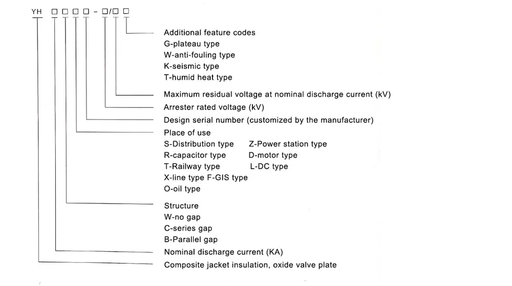
This product model is compiled in accordance with JB/T 8459-2006 "Method for Preparing Surge Arrester Product Models". Wujianyuan products comply with GB 11032-2000 "AC Gapless Metal Oxide Surge Arrester" standards: Youjianyuan products comply with JBT 9672-2005 " Standard for metal oxide arresters with series gaps. Important parameters and configuration methods that are not clearly defined in the above standards shall be revised and implemented in accordance with the requirements of DL/T 620-1997 "Overvoltage Protection and Insulation Cooperation of AC Electrical Devices".
3.1 The normal usage conditions of conventional products are as follows:
(1) Ambient temperature: not higher than +40C, not lower than -40C;
(2) Altitude: no more than 3000m;
(3) Power frequency: 502Hz; 602Hz;
(4) Maximum wind speed: 35m/s;
(5) Cleaning-free conditions: areas with moderate pollution and below;
(6) For products without gaps, the long-term applied power frequency voltage shall not exceed the continuous operating voltage of the arrester.
(7) For products with gaps, the short-term power frequency voltage increase at the installation point shall not exceed the rated voltage of the arrester.
3.2 For long-term use under the following abnormal conditions, the lightning arrester needs to be specially made and should be stated when ordering:
(1) The temperature or altitude exceeds the standard (such as plateau, tropical, cold zone, fully enclosed cabinet, close to electric furnace, etc.)
(2) The use environment contains severe moisture or corrosive gas impurities (such as water, salt fields, chemical plants, etc.):
(3) Strong ultraviolet radiation (such as plateaus, dry areas with strong sunshine, etc.);
(4) Extremely polluted areas (such as mining working faces, construction site working faces, etc.).
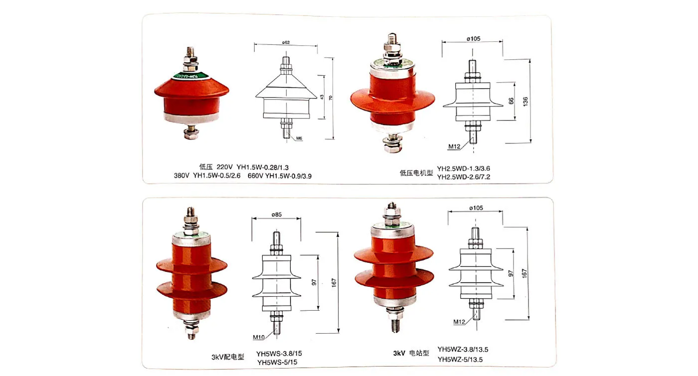
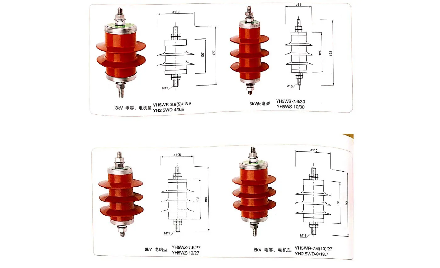
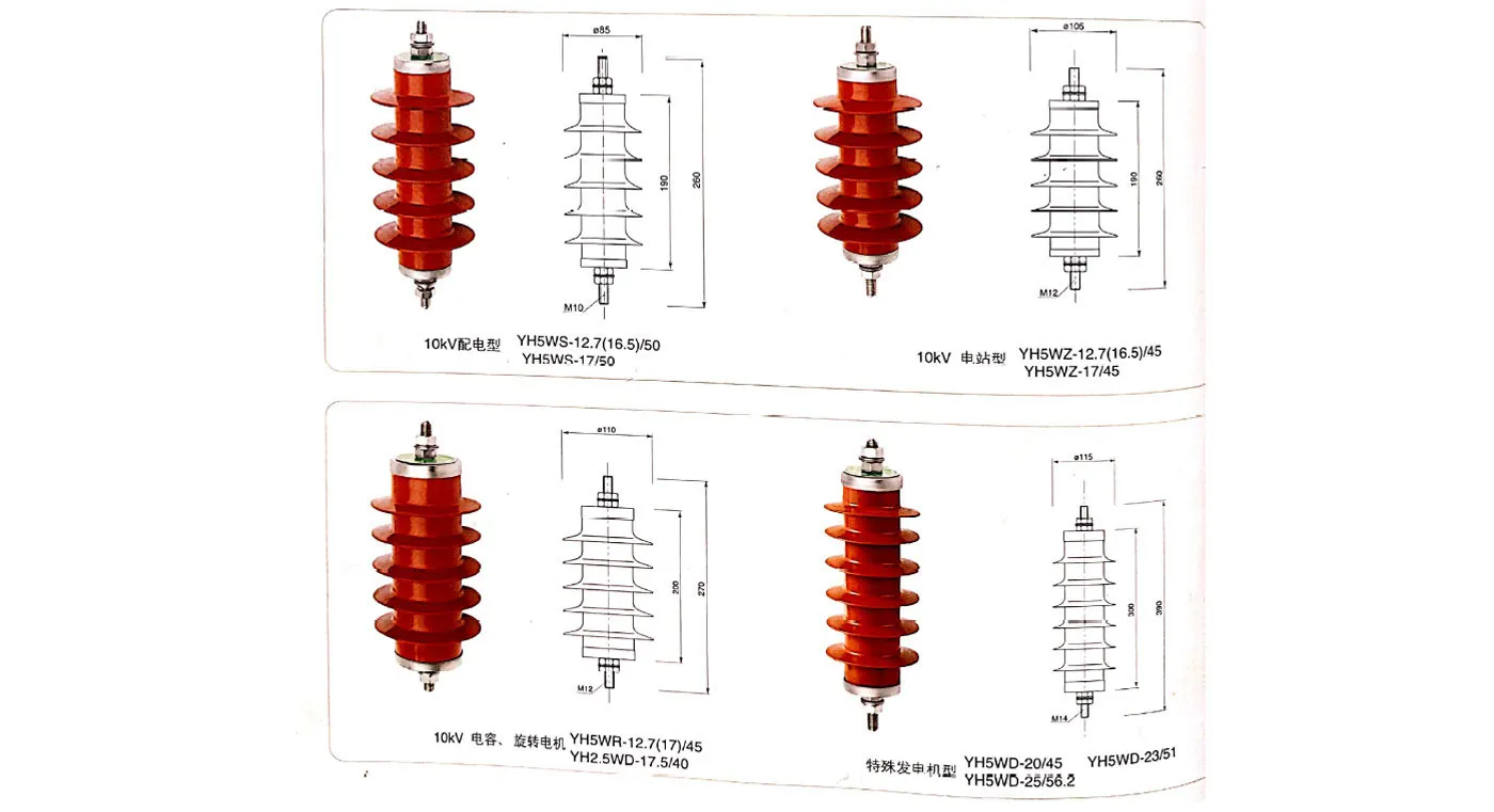
The following is a typical parameter table of conventional arresters, arranged from low to high voltage levels to facilitate user search.
Note:
1) Each national standard model can be derived from several models of products. Due to space limitations, we will not list them one by one. If users have any questions about the models, they can directly consult our company's technical department;
2) In the "System Nominal Voltage" column, the data with * indicates the motor rated voltage corresponding to the motor protection arrester; in the "Power Frequency Discharge Voltage" column, the data with * indicates the power frequency tolerance of high-voltage arresters above 110kV. Voltage effective value;
3) Due to the many uses and voltage levels, the impulse current value corresponding to the impulse residual voltage of the 30/60 operation of the arrester is not specified;
4) Most products can be equipped with accessories such as disconnectors and counters. If they are equipped with disconnectors, add "L", and if they are equipped with counters, add "J" after the model number.
| Voltage level | Place of use | System nominal voltage (kV) effective value | National standard model of lightning arrester | Arrester rated voltage (kV) effective value | Gapless arrester | Gap arrester | Residual voltage (kV) peak value (not greater than) | μS square wave flow capacity (A) | 4/10 Large current withstand capability (kA) | ||||||
| Arrester continuous operating voltage (kV) effective value | DC 1mA reference voltage (kV) is not less than | Maximum leakage at 0.75 times DC reference voltage (μA) | The effective value of power frequency discharge voltage (kV) is not less than | 1.2/50 The peak value of impulse discharge voltage (kV) is not greater than | Maximum conductive current (μA) | 8/20Under lightning impulse current | 30/60 operating surge current | Under 1/4 steep wave impulse current | |||||||
| low pressure | Distribution type | 0.22 | YH1.5W-0.28/1.3 | 0.28 | 0.24 | 0.6 | 50 | - | - | - | 1.3 | - | - | 75 | 25 |
| 0.38 | YH1.5W-0.5/2.6 | 0.5 | 0.42 | 1.2 | 50 | - | - | - | 2.6 | - | - | 75 | 25 | ||
| Motor type | 0.66* | YH2.5WD-1.3/3.6 | 1.3 | 0.95 | 1.8 | 50 | - | - | - | 3.6 | - | - | 200 | 40 | |
| 1.14* | YH2.5WD-2.6/7.2 | 2.6 | 1.9 | 3.6 | 50 | - | - | - | 7.2 | - | - | 200 | 40 | ||
| 3kV | Distribution type | 3 | YH5WS-3.8/15 | 3.8 | 2.0 | 7.5 | 50 | - | - | - | 15.0 | 12.8 | 17.3 | 75 | 40 |
| 3 | YH5WS-5/15 | 5 | 4.0 | 7.5 | 50 | - | - | - | 15.0 | 12.8 | 17.3 | 75 | 40 | ||
| 3 | YH5CS-3.8/13.5 | 3.8 | - | - | - | 9.0 | 13.5 | 20 | 13.5 | 11.4 | 15.0 | 75 | 40 | ||
| Power station type | 3 | YH5WZ-3.8/13.5 | 3.8 | 2.0 | 7.2 | 50 | - | - | - | 13.5 | 11.5 | 15.5 | 200 | 65 | |
| 3 | YH5WZ-5/13.5 | 5 | 4.0 | 7.2 | 50 | - | - | - | 13.5 | 11.5 | 15.5 | 200 | 65 | ||
| 3 | YH5CZ-3.8/12.0 | 3.8 | - | - | - | 8.0 | 12.0 | 20 | 12.0 | 10.2 | 13.5 | 200 | 65 | ||
| Capacitive type | 3 | YH5WR-3.8/13.5 | 3.8 | 2.0 | 7.2 | 50 | - | - | - | 13.5 | 10.5 | - | 400 | 65 | |
| 3 | YH5WR-5/13.5 | 5 | 4.0 | 7.2 | 50 | - | - | - | 13.5 | 10.5 | - | 400 | 65 | ||
| 3 | YH5CR-3.8/12.0 | 3.8 | - | - | - | 8.0 | 12.0 | 20 | 12.0 | 9.6 | - | 400 | 65 | ||
| Generator type | 3.15* | YH5WD-3.8/9.5 | 3.8 | 2.0 | 5.7 | 50 | - | - | - | 9.5 | 7.6 | 10.7 | 400 | 65 | |
| 3.15* | YH5WD-4/9.5 | 4 | 3.15 | 5.7 | 50 | - | - | - | 9.5 | 7.6 | 10.7 | 400 | 65 | ||
| 3.15* | YH5CD-3.8/8.6 | 3.8 | - | - | - | 7.5 | 8.6 | 20 | 8.6 | 6.9 | 9.8 | 400 | 65 | ||
| Electric model | 3.15* | YH2.5WD-3.8/9.5 | 3.8 | 2.0 | 5.7 | 50 | - | - | - | 9.5 | 7.6 | 10.7 | 200 | 65 | |
| 3.15* | YH2.5WD-4/9.5 | 4 | 3.15 | 5.7 | 50 | - | - | - | 9.5 | 7.6 | 10.7 | 200 | 65 | ||
| 3.15* | YH2.5CD-3.8/8.6 | 3.8 | - | - | - | 7.5 | 8.6 | 20 | 8.6 | 6.9 | 9.8 | 200 | 65 | ||
| neutral point type | 3.15* | YH1.5W-2.4/6 | 2.4 | 1.9 | 3.4 | 50 | - | - | - | 6.0 | 5.0 | - | 200 | 65 | |
| 6kV | Distribution type | 6 | YH5WS-7.6/30 | 7.6 | 4.0 | 15.0 | 50 | - | - | - | 30.0 | 25.6 | 34.6 | 75 | 40 |
| 6 | YH5WS-10/30 | 10 | 8.0 | 15.0 | 50 | - | - | - | 30.0 | 25.6 | 34.6 | 75 | 40 | ||
| 6 | YH5CS-7.6/27 | 7.6 | - | - | - | 16.0 | 27.0 | 20 | 27.0 | 22.5 | 30.0 | 75 | 40 | ||
| Power station type | 6 | YH5WZ-7.6/27 | 7.6 | 4.0 | 14.4 | 50 | - | - | - | 27.0 | 23.0 | 31.0 | 200 | 65 | |
| 6 | YH5WZ-10/27 | 10 | 8.0 | 14.4 | 50 | - | - | - | 27.0 | 23.0 | 31.0 | 200 | 65 | ||
| 6 | YH5CZ-7.6/24 | 7.6 | - | - | - | 16.0 | 24.0 | 20 | 24.0 | 20.4 | 27.0 | 200 | 65 | ||
| Capacitive type | 6 | YH5WR-7.6/27 | 7.6 | 4.0 | 14.4 | 50 | - | - | - | 27.0 | 21.0 | - | 400 | 65 | |
| 6 | YH5WR-10/27 | 10 | 8.0 | 14.4 | 50 | - | - | - | 27.0 | 21.0 | - | 400 | 65 | ||
| 6 | YH5CR-7.6/24 | 7.6 | - | - | - | 16.0 | 24.0 | 20 | 24.0 | 19.5 | - | 400 | 65 | ||
| Generator type | 6.3* | YH5WD-7.6/18.7 | 7.6 | 4.0 | 11.2 | 50 | - | - | - | 18.7 | 15.0 | 21.0 | 400 | 65 | |
| 6.3* | YH5WD-8/18.7 | 8 | 6.3 | 11.2 | 50 | - | - | - | 18.7 | 15.0 | 21.0 | 400 | 65 | ||
| 6.3* | YH5CD-7.6/17 | 7.6 | - | - | - | 15.0 | 17.0 | 20 | 17.0 | 13.8 | 19.6 | 400 | 65 | ||
| Electric model | 6.3* | YH2.5WD-7.6/18.7 | 7.6 | 4.0 | 11.2 | 50 | - | - | - | 18.7 | 15.0 | 21.0 | 200 | 65 | |
| 6.3* | YH2.5WD-8/18.7 | 8 | 6.3 | 11.2 | 50 | - | - | - | 18.7 | 15.0 | 21.0 | 200 | 65 | ||
| 6.3* | YH2.5CD-7.6/17 | 7.6 | - | - | - | 15.0 | 17.0 | 20 | 17.0 | 13.8 | 19.6 | 200 | 65 | ||
| neutral point type | 6.3* | YH1.5W-4.8/12 | 4.8 | 3.8 | 6.8 | 50 | - | - | - | 12.0 | 10.0 | - | 200 | 65 | |
| 10kV | Distribution type | 10 | YH5WS-12.7/50 | 12.7 | 6.6 | 25 | 50 | - | - | - | 50 | 42.5 | 57.5 | 75 | 40 |
| 10 | YH5WS-17/50 | 17 | 13.6 | 25 | 50 | - | - | - | 50 | 42.5 | 57.5 | 75 | 40 | ||
| 10 | YH5CS-12.7/45 | 12.7 | - | - | - | 26.0 | 45 | 20 | 45 | 38.4 | 51.0 | 75 | 40 | ||
| Power station type | 10 | YH5WZ-12.7/45 | 12.7 | 6.6 | 24 | 50 | - | - | - | 45 | 38.3 | 51.8 | 200 | 65 | |
| 10 | YH5WZ-17/45 | 17 | 13.6 | 24 | 50 | - | - | - | 45 | 38.3 | 51.8 | 200 | 65 | ||
| 10 | YH5CZ-12.7/41 | 12.7 | - | - | - | 26.0 | 41 | 20 | 41 | 35.0 | 46.0 | 200 | 65 | ||
| Capacitive type | 10 | YH5WR-12.7/46 | 12.7 | 6.6 | 24 | 50 | - | - | - | 46 | 35.0 | - | 400 | 65 | |
| 10 | YH5WR-17/46 | 17 | 13.6 | 24 | 50 | - | - | - | 46 | 35.0 | - | 400 | 65 | ||
| 10 | YH5CR-12.7/41 | 12.7 | - | - | - | 26.0 | 41 | 20 | 41 | 33.0 | - | 400 | 65 | ||
| Generator type | 10.5* | YH5WD-12.7/31 | 12.7 | 6.6 | 18.6 | 50 | - | - | - | 31 | 25 | 34.7 | 400 | 65 | |
| 10.5* | YH5WD-13.5/31 | 13.5 | 10.5 | 18.6 | 50 | - | - | - | 31 | 25 | 34.7 | 400 | 65 | ||
| 10.5* | YH5CD-12.7/28 | 12.7 | - | - | - | 25.0 | 28.0 | 20 | 28 | 22.5 | 32.0 | 400 | 65 | ||
| 13.8* | YH5WD-17.5/40 | 17.5 | 13.8 | 24.4 | 50 | - | - | - | 40.0 | 32.0 | 44.8 | 400 | 65 | ||
| 15.75* | YH5WD-20/45 | 20 | 15.75 | 28.0 | 50 | - | - | - | 45.0 | 36.0 | 50.4 | 400 | 65 | ||
| 18.0* | YH5WD-23/51 | 23 | 18.0 | 31.9 | 50 | - | - | - | 51.0 | 40.8 | 57.2 | 400 | 65 | ||
| 20.0* | YH5WD-25/56.2 | 25 | 20.0 | 35.4 | 50 | - | - | - | 56.2 | 45.0 | 62.9 | 400 | 65 | ||
| Electric model | 10.5* | YH2.5WD-12.7/31 | 12.7 | 6.6 | 18.6 | 50 | - | - | - | 31 | 25 | 34.7 | 200 | 65 | |
| 10.5* | YH2.5WD-13.5/31 | 13.5 | 10.5 | 18.6 | 50 | - | - | - | 31 | 25 | 34.7 | 200 | 65 | ||
| 10.5* | YH2.5CD-12.7/28 | 12.7 | - | - | - | 25.0 | 28.0 | 20 | 28 | 22.5 | 32.0 | 200 | 65 | ||
| Neutral point type | 10.5* | YH1.5W-8/19 | 8 | 6.4 | 11.4 | 50 | - | - | - | 19.0 | 15.9 | - | 400 | 65 | |
| 13.8* | YH1.5W-10.5/23 | 10.5 | 8.4 | 14.9 | 50 | - | - | - | 23.0 | 19.2 | - | 400 | 65 | ||
| 15.75* | YH1.5W-12/26 | 12 | 9.6 | 17.0 | 50 | - | - | - | 26.0 | 21.6 | - | 400 | 65 | ||
| 18.0* | YH1.5W-13.7/29.2 | 13.7 | 11.0 | 19.5 | 50 | - | - | - | 29.2 | 24.3 | - | 400 | 65 | ||
| 20.0* | YH1.5W-15.2/31.7 | 15.2 | 12.0 | 21.6 | 50 | - | - | - | 31.7 | 26.4 | - | 400 | 65 | ||
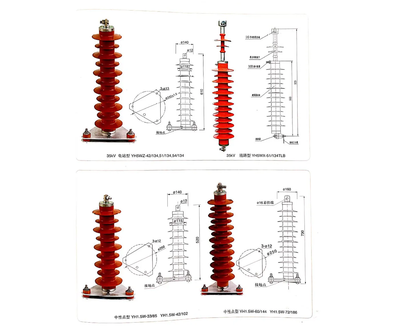
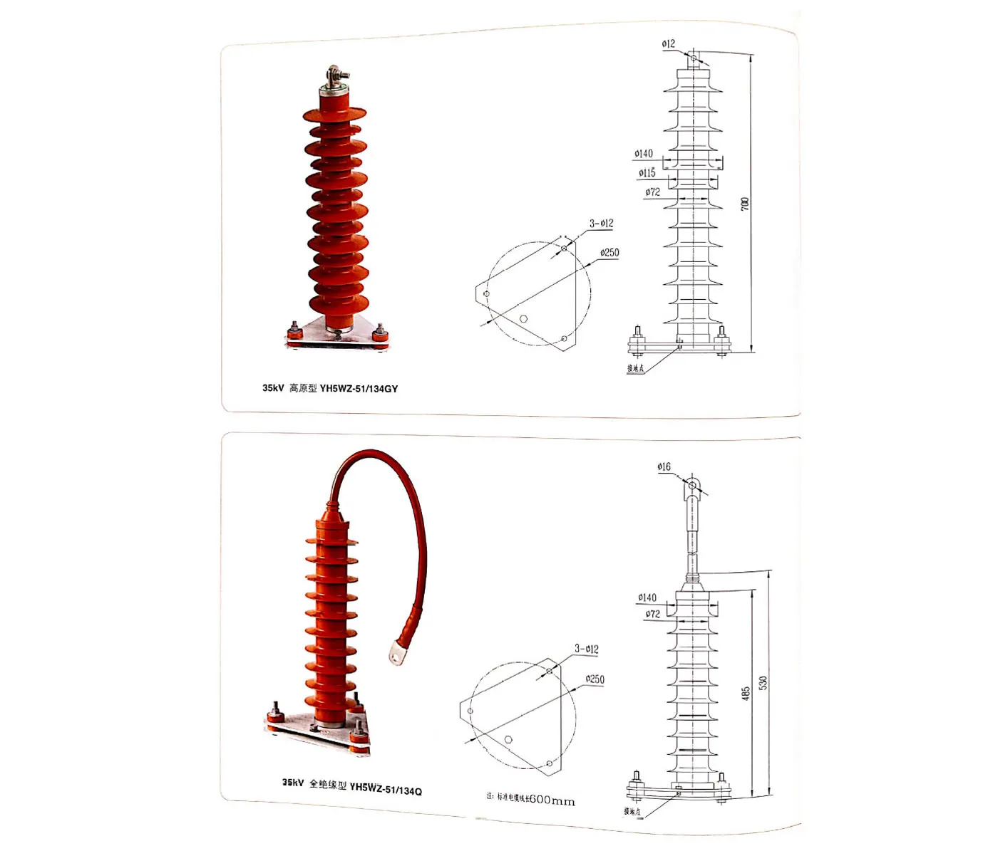
| 35kV | Power station type | 35 | YH5WZ-51/134 | 51 | 40.8 | 73 | 50 | - | - | - | 134 | 114 | 154 | 400 | 65 |
| 35 | YH5WZ-42/134 | 42 | 23.4 | 73 | 50 | - | - | - | 134 | 114 | 154 | 400 | 65 | ||
| 35 | YH5CZ-42/124 | 42 | - | - | - | 80.0 | 124 | 20 | 124 | 100 | 143 | 400 | 65 | ||
| Capacitive type | 35 | YH5WR-51/134 | 51 | 40.8 | 73 | 50 | - | - | - | 134 | 105 | - | 400 | 65 | |
| 35 | YH5WR-42/134 | 42 | 23.4 | 73 | 50 | - | - | - | 134 | 105 | - | 400 | 65 | ||
| 35 | YH5CR-42/124 | 42 | - | - | - | 80.0 | 124 | 20 | 124 | 100 | - | 400 | 65 | ||
| Line type | 35 | YH5WX-51/134 | 51 | 40.8 | 73 | 50 | - | - | - | 134 | 114 | 154 | 400 | 65 | |
| 35 | YH5WX-54/150 | 54 | 43.2 | 77 | 50 | - | - | - | 150 | 128 | 169 | 400 | 65 | ||
| 35 | YH5CX-42/120 | 42 | - | - | - | 80.0 | 120 | 20 | 120 | 100 | 138 | 400 | 65 | ||
| 35 | YH5CX-42/150 | 42 | - | - | - | 80.0 | 150 | 20 | 150 | 128 | 169 | 400 | 65 | ||
| Neutral point type | 35 | YH1.5W-30/80 | 30 | 24 | 44 | 50 | - | - | - | 80 | 67.5 | - | 400 | 65 | |
| 66kV | Power station type | 66 | YH5WZ-84/221 | 84 | 67.2 | 121 | 50 | - | - | - | 221 | 188 | 254 | 600 | 65 |
| 66 | YH5WZ-90/235 | 90 | 72.5 | 130 | 50 | - | - | - | 235 | 201 | 270 | 600 | 65 | ||
| 66 | YH10WZ-84/221 | 84 | 67.2 | 121 | 50 | - | - | - | 221 | 188 | 248 | 600 | 100 | ||
| 66 | YH10WZ-90/235 | 90 | 72.5 | 130 | 50 | - | - | - | 235 | 201 | 264 | 600 | 100 | ||
| Line type | 66 | YH5WX-96/250 | 96 | 75 | 140 | 50 | - | - | - | 250 | 213 | 288 | 600 | 65 | |
| 66 | YH5WX-96/275 | 96 | 75 | 154 | 50 | - | - | - | 275 | 234 | 316 | 600 | 65 | ||
| 110kV | Power station type | 110 | YH5WZ-100/260 | 100 | 78 | 145 | 50 | - | - | - | 260 | 221 | 299 | 600 | 65 |
| 110 | YH5WZ-102/266 | 102 | 79.6 | 148 | 50 | - | - | - | 266 | 226 | 305 | 600 | 65 | ||
| 110 | YH5WZ-108/281 | 108 | 84 | 157 | 50 | - | - | - | 281 | 239 | 323 | 600 | 65 | ||
| 110 | YH10WZ-100/260 | 100 | 78 | 145 | 50 | - | - | - | 260 | 221 | 291 | 600 | 100 | ||
| 110 | YH10WZ-102/266 | 102 | 79.6 | 148 | 50 | - | - | - | 266 | 226 | 297 | 600 | 100 | ||
| 110 | YH10WZ-108/281 | 108 | 84 | 157 | 50 | - | - | - | 281 | 239 | 315 | 600 | 100 | ||
| Line type | 110 | YH5WX-108/281 | 108 | 84 | 157 | 50 | - | - | - | 281 | 239 | 323 | 600 | 65 | |
| 110 | YH5WX-108/309 | 108 | 84 | 173 | 50 | - | - | - | 309 | 263 | 348 | 600 | 65 | ||
| 110 | YH10WX-108/281 | 108 | 84 | 157 | 50 | - | - | - | 281 | 239 | 315 | 600 | 100 | ||
| 110 | YH10WX-108/309 | 108 | 84 | 173 | 50 | - | - | - | 309 | 263 | 348 | 600 | 100 | ||
| 110 | YH5CX-90/260 | 90 | - | 130 | 50 | 170* | 525* | - | 260 | - | 292 | 400 | 65 | ||
| 110 | YH10CX-90/260 | 90 | - | 130 | 50 | 170* | 525* | - | 260 | - | 292 | 600 | 100 | ||
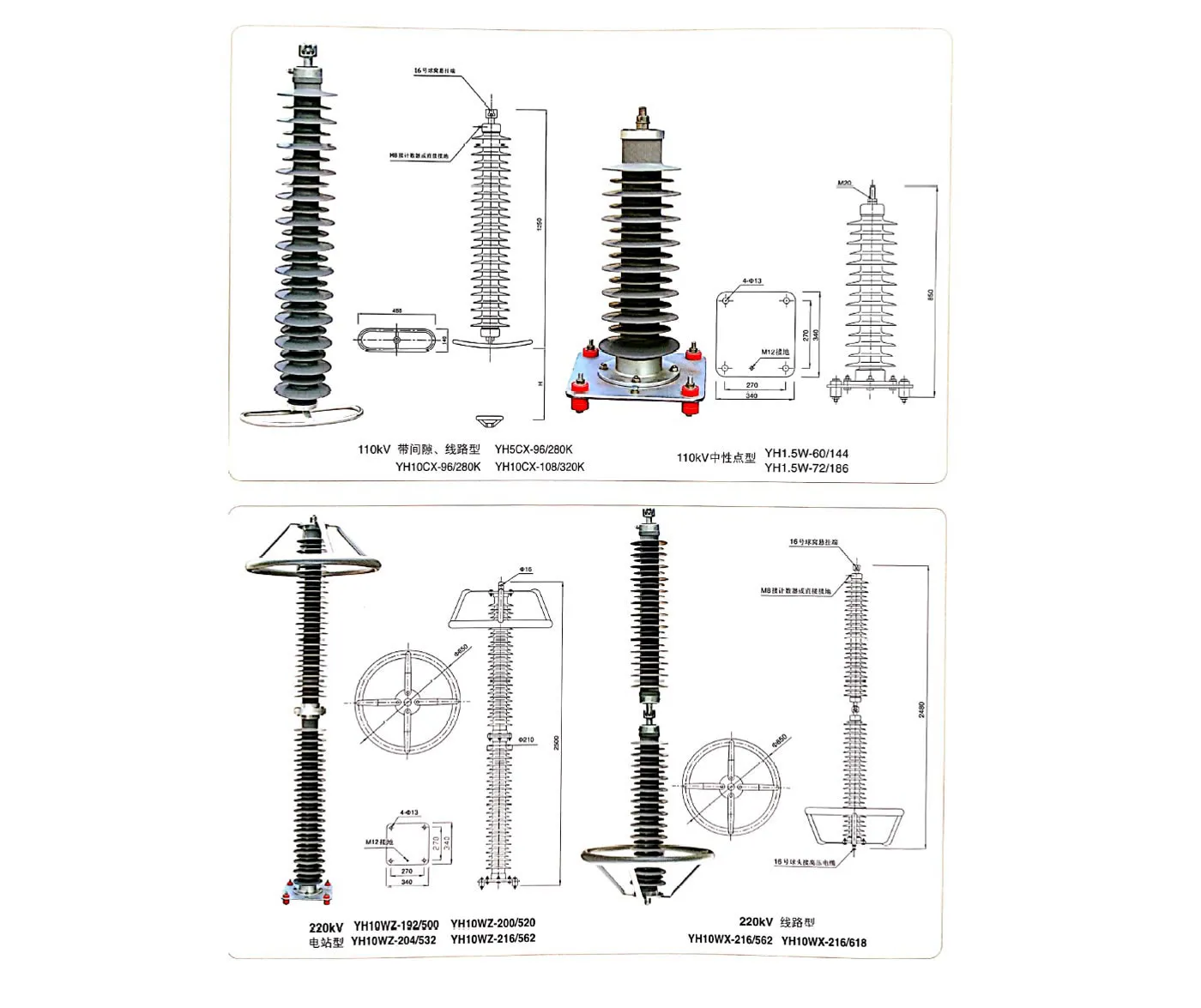
| 110 | YH10CX-96/280 | 96 | - | 140 | 50 | 170* | 525* | - | 280 | - | 314 | 600 | 100 | ||
| 110 | YH10CX-102/296 | 102 | - | 148 | 50 | 170* | 525* | - | 296 | - | 332 | 600 | 100 | ||
| Neutral point type | 110 | YH1.5W-60/144 | 60 | 48 | 85 | 50 | - | - | - | 144 | 135 | - | 400 | 65 | |
| 110 | YH1.5W-72/186 | 72 | 58 | 103 | 50 | - | - | - | 186 | 174 | - | 400 | 65 | ||
| 220kV | Power station type | 220 | YH10WZ-192/500 | 192 | 150 | 280 | 50 | - | - | - | 500 | 426 | 560 | 800 | 100 |
| 220 | YH10WZ-200/520 | 200 | 156 | 290 | 50 | - | - | - | 520 | 442 | 582 | 800 | 100 | ||
| 220 | YH10WZ-204/532 | 204 | 159 | 296 | 50 | - | - | - | 532 | 452 | 594 | 800 | 100 | ||
| 220 | YH10WZ-216/562 | 216 | 168.5 | 314 | 50 | - | - | - | 562 | 478 | 630 | 800 | 100 | ||
| Line type | 220 | YH10WX-216/562 | 216 | 168 | 314 | 50 | - | - | - | 562 | 487 | 630 | 600 | 100 | |
| 220 | YH10WX-216/618 | 216 | 168 | 346 | 50 | - | - | - | 618 | 526 | 693 | 600 | 100 | ||
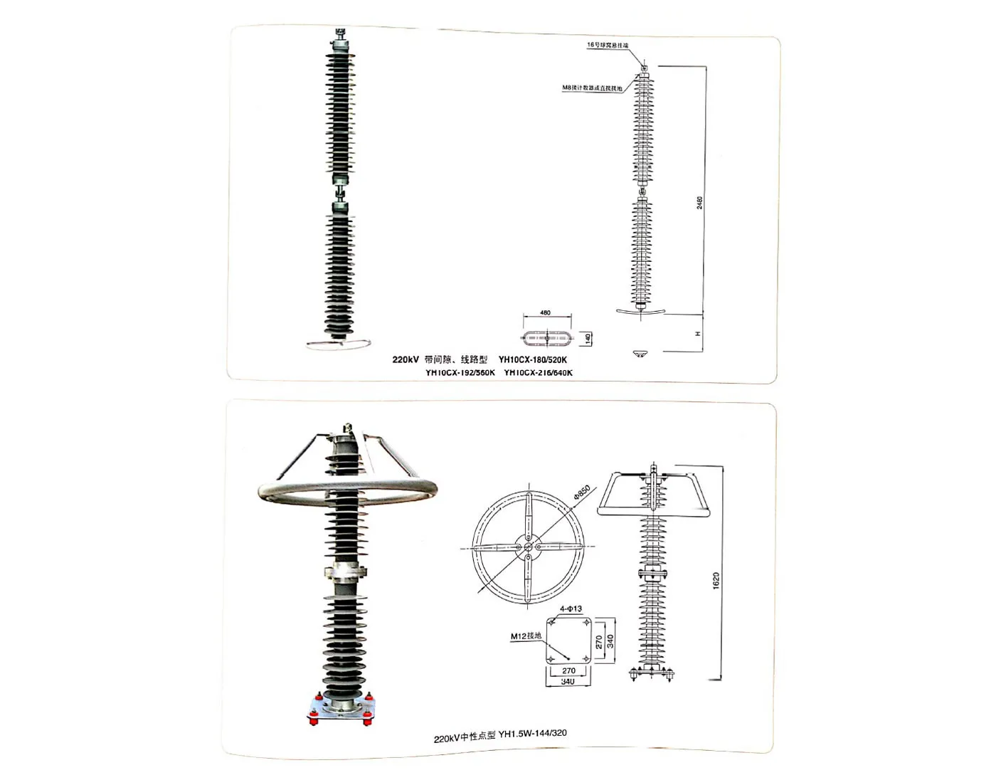
| 220 | YH10CX-185/520 | 180 | - | 260 | 50 | 340* | 900* | - | 520 | 584 | 600 | 100 | |||
| 220 | YH10CX-192/560 | 192 | - | 280 | 50 | 340* | 900* | - | 560 | - | 628 | 600 | 100 | ||
| 220 | YH10CX-204/592 | 204 | - | 296 | 50 | 340* | 900* | - | 592 | - | 664 | 600 | 100 | ||
| Neutral point type | 220 | YH1.5W-144/320 | 144 | 116 | 205 | 50 | - | - | - | 320 | 299 | - | 600 | 65 | |
| 27.5kV | Railway type | 27.5 | YH5WT-42/120 | 42 | 34 | 65 | 50 | - | - | - | 120 | 98 | 138 | 400 | 65 |
| 55kV | 55 | YH5WT-84/240 | 84 | 68 | 130 | 50 | - | - | - | 240 | 276 | 276 | 400 | 65 | |



GET A QUOTE